Sealing Business
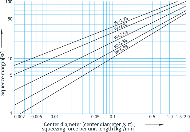
Figure 1. Reaction force at installation
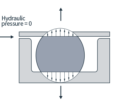
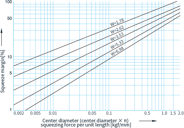
Figure 2. Reaction force at hydraulic load
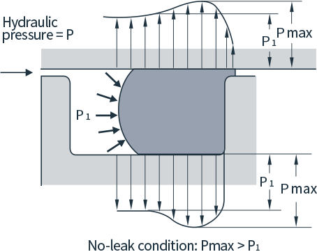
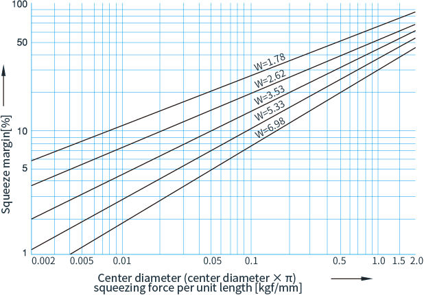
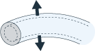
Figure 3. For static cylindrical surface use
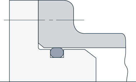
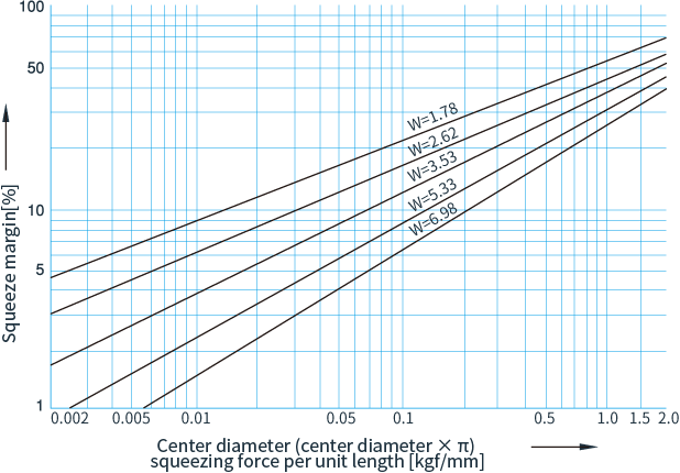
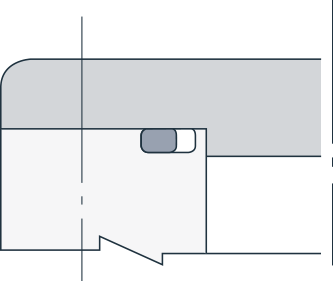
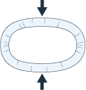
Figure 4. For static flat surface use
Under low pressure conditions, the O-ring is hermetically sealed by the squeeze margin. It deforms as the pressure increases, using the resulting tightening force to create the seal. Under high pressure, the O-ring starts to extrude from the gap between the piston and cylinder, and from between the rod and sleeve as shown in Figure 6-3. This can lead to damage, so it is important to keep this gap as small as possible. An effective way to prevent extrusion is to use a backup ring.
Figure 6-1.

Figure 6-2.
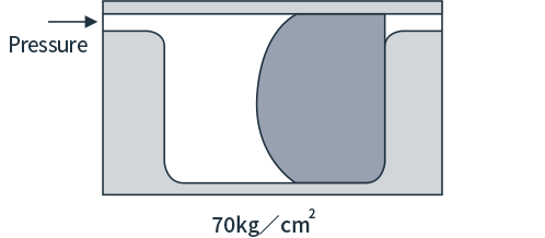
Figure 6-3.
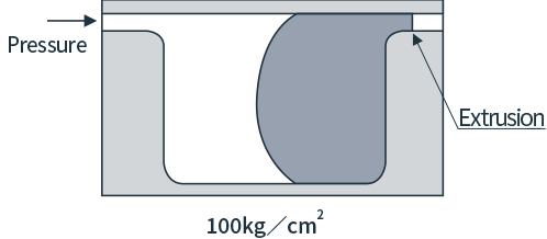
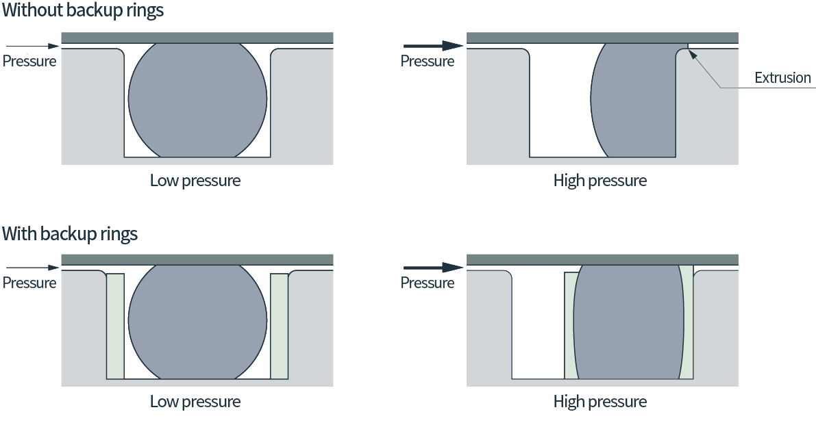
Figure 7-1.
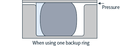
Figure 7-2.
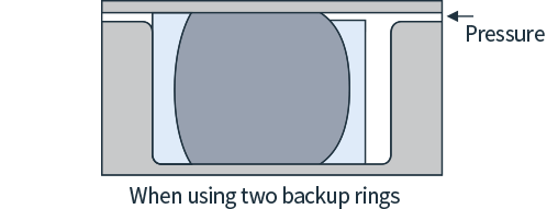
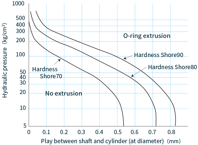
Figure 8.O-ring handling precautions
Figure 9.
Figure 10.
| Name | Phenomenon | Cause | Countermeasures |
|---|---|---|---|
Swelling
 |
The rubber softens and the entire O-ring enlarges. | The operating liquid penetrates the rubber material of the O-ring. | Change to a suitable rubber material. |
Extraction
 |
The rubber hardens and the entire O-ring shrinks. | The softening agent contained in the rubber material of the O-ring is extracted by the operating liquid. | Change to a suitable rubber material. |
Permanent deformation
 |
The O-ring is squeezed and does not return to its original shape. | 1.The usage temperature is too high. | 1.Change to a rubber material with good heat resistance. |
| 2.Squeeze margin is too large. | 2.Review the groove dimension or the O-ring size. | ||
Extrusion
 |
Partial tearing or around the entire circumference of the O-ring | The O-ring extrudes into the clearance between the groove and the opposite surface, tearing at the edge of the groove. | 1.Reduce the clearance with the groove. |
| 2.Use a very hard O-ring or use it together with a backup ring. | |||
Ozone cracks
 |
There are cracks perpendicular to the direction of the stress. | 1. A rubber material with poor ozone resistance was used in a strong ozone atmosphere. | 1.Change to a rubber material with good ozone resistance. |
| 2.The O-ring was used stretched unnecessarily. | 2.Change the groove dimension or O-ring size. | ||
| 3.Insufficient amount of grease applied. | 3.Apply sufficient grease when installing. | ||
Twisting
 |
O-ring is twisted and deformed. | 1.The depth and width of the grooves are not equal. | 1. Make the depth and width of the grooves equal. |
| 2.Inappropriate finish for the inner surface and the bottom groove surface of the cylinder. | 2.Change the finish of the inner surface of the cylinder to 1.5S and the groove bottom surface to 3S. | ||
| 3.There is an eccentric motion. | 3.Eliminate the eccentric motion. | ||
| 4.The O-ring was installed twisted. | 4.Use grease to prevent twisting during installation. | ||
Nibbling |
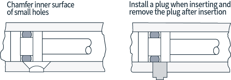
Small bits are taken off the O-ring in several places | 1.Bits were torn off by the edges of the small hole of the cylinder. | 1.Make a design change, such as chamfering the small holes. |
| 2.Bits were torn off by sharp edges and screw threads during installation. | 2Use a jig when installing. | ||
Abrasion
 |
The O-ring shows wear in the direction of the motion. | 1.The surface finish of the inner surface of the cylinder is too rough. | 1.Change the surface finish of the cylinder’s inner surface to 1.5S. |
| 2.Poor lubrication | 2.Lubricate better. | ||
| 3.Squeeze margin is too large. | 3.Change to a thicker O-ring to provide appropriate squeeze margin. | ||
| 4.Contamination such as dust, metal objects, etc. | 4.Use a filter to prevent foreign objects from entering. | ||
Hardening
 |
The O-ring becomes hard and cracks when bent. | The operating temperature exceeds the heat resistant temperature of the rubber material of the O-ring. | 1.Change to a rubber material with good heat resistance. |
| 2.Lower the temperature. |